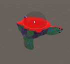
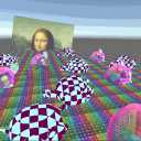
Unlit Dynamic Decals/Projection Often when doing VFX you want stuff to stick to the floor. Even when that floor is uneven. Or decals to make existing geometry more interresting, or you want blob shadows on uneven floor, or some other use-cases in the same direction.
(note: I used the free “Nature Starter Kit 2” from the Unity Asset store throughout this tutorial)
Unity has the concept of a “projector” for that, but I have to admit I dont quite trust them.
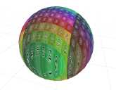
Polar Coordinates So far whenever we used coordinates we had a clear grid of 2 or 3 axes in which we could manipulate things and push them around. There were multiple spaces of those like object, world, screen, uv space and maybe more but the base rules were always the same most of the time. That pushing things to the right, pushes them to the right, up is up etc… This is called “cartesian coordinates”.
Object Outlines I have made multiple tutorials about outlines already, doing them with a inverted hull, as a postprocessing effect using the depth and normal buffers or by sampling neighboring pixels of a sprite, but I want to add another technique to those. It uses the same base idea of sampling neighboring pixels as the sprite based one, but can be applied to 3d models. It uses a postprocessing effect, yet can be applied to distinct objects you choose.
Graphics.DrawProcedural The last tutorial was about compute shader basics, how to generate values, read them back to the cpu and use them. One critical aspect in all that is that copying data from the cpu to the gpu (from the ram to the vram) or back takes some time, so wouldn’t it be neat if there was a way to just render the data directly from the GPU without copying it around?
Compute Shader So far we always used shaders to render with a fixed pipeline into textures, but modern graphics card can do way more than just that (sometimes they’re also referred to as GPGPU for “general purpose graphics processing unit” because of that). To do things that arent in the fix pipeline we’re using so far we have to use compute shaders.
If you’re asking yourself why we’d do that, the CPU is performant enough, especially once we use multithreading then I’m here to tell you that you’re 100% correct.
Sprite Outlines I already talked about 2 ways of generating outlines in your programs, by analyzing the depth and normals of your scene or by rendering the model twice with a hull. Both of those assume we’re using opaque meshes that write into the depth buffer, if we’re using 2d sprites neither approach works. The approach for this tutorial uses the alpha channel of a texture to generate 2d outlines.
Basic Implementation The idea is that we sample the texture at multiple spots around the uv point and remember the biggest value of the alpha channel we find.
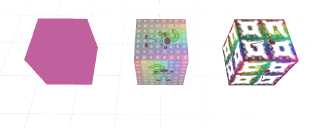
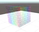
Instancing and Material Property Blocks Current State I’m going to go off a basic unlit shader in this tutorial. In all tutorials since that one we always set the properties at a “per material” basis. This allows us to do everything we ever need to do in theory, but depending on the circumstances it might also force us to use tons of different materials. This not only makes a scene harder to author, but can also significantly slow down your game as by default objects with different materials cannot be instanced together and switching drawcalls is one of the main performance sinks of rendering.
Inverse Lerp and Remap In a previous tutorial I explained how the builtin lerp function works. Now I want to add the inverse lerp as well as the remap functions to this. They’re not builtin functions so we’ll have to write our own implementations. While this is a tutorial that focuses on explaining mathematical concepts, they resolve into basic addition and multiplication pretty quickly so I hope it isn’t too hard.
Example Shader The base shader is pretty barebones, a little more complex than a completely unlit one.
Partial Derivatives (fwidth) The partial derivative functions ddx, ddy and fwidth are some of the least used hlsl functions and they look quite confusing at first, but I like them a lot and I think they have some straightforward useful use cases so I hope I can explain them to you. Since I’m explaining straightforward functions you don’t have to know a lot of shader programming for this, but you should have a rough overview over how to render simple things with shaders in unity.
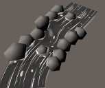
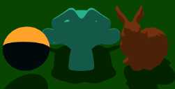
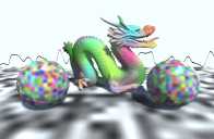
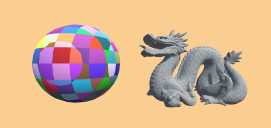
Handling Depth for Spheretracing In the last 2 tutorials of the volumetric rendering series I showed how to trace 3d signed distance fields and how to shade the result. In my opinion the biggest drawback of the state of the shader so far is the way that independent objects interact with each other and with regular meshes. They either don’t write to the depth buffer at all, or with the shape of the mesh that’s used for them and the depth check is similarly lacking.
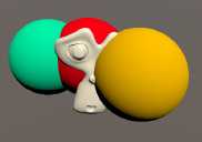
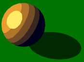
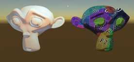
Spheretracing with Shading In a previous tutorial I showed how to trace signed distance functions to reveal their silouette. In this one I will show you how to expand that shader to add simple lighting and make the objects look more tangible.
Architecture Changes In the previous shader we returned a solid color after finding a surface the ray collides with. To add lighting or other effects we have to expand this part. To keep the shader as readable as possible we’ll do a function call in this place and return the result of the function.
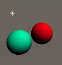
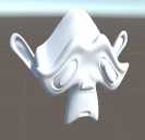
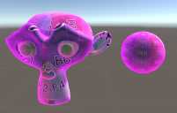
Spheretracing Basics Raytracing is a huge topic and one that seems scary and unapproachable for many. One specific kind of raytracing we can do with signed distance fields which I have explored in the 2d space in previous tutorials is called spheretracing. In this first tutorial we’ll just trace the silouette of a sphere, but in future tutorials I’ll give examples how to make more complex shapes and do lighting.
As the base of the shader we’ll use a basic unlit shader, so you can do this tutorial when you’re fairly new to shaders.
Dithering We often use gradients of some kind in shaders, but there are cases where we’re limited to less shades of colors than we want to express. One common technique to fake having many different colors with only a few is dithering. In this tutorial I explain how to dither between two colors based on a given ratio, but it’s also possible to use dithering for more shades of color with more complex algorithms.
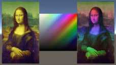
HSV Color Space So far we always used RGB colors in our shaders, meaning the components of our color vector always map to the red green and blue components of the color. This is great if we want to render the color or tint it, but adjusting the hue or saturation becomes very bothersome. For those kinds of operations we can use the HSV color space. In addition to the HSV color space there are also other similar color spaces, like the HSL or CIE color models.
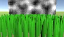
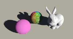
Halftone Shading This tutorial is on another common toon shading technique called halftone shading, unlike normal shading it only uses full lit or full unlit as colors, but it doesn’t create a hard cut either. Instead it uses a pattern to decide which pixels are lit and which aren’t and the chance of a pixel being lit gets higher the brighter the pixel would be with a normal lighting method. To understand this tutorial I recommend reading and understanding the tutorial about custom lighting methods and the tutorial about generating screenspace texture coordinates.
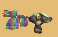
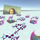
Screenspace Textures There are many techniques how to generate texture coordinates. Previous tutorials explain how to use UV coordinates and how to generate coordinates based on planar and triplanar mapping. In this one we’ll use the position of the pixel on the screen as the coordinate.
On it’s own the effect just looks kind of weird, which can also be used as a aesthetic choice, but it can be used for many cool effects I’ll go into in the future.
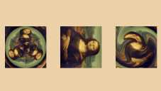
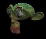
Texture Dissolve This tutorial is about how to make Meshes dissolve in the pattern of a texture. We will use a surface shader for this tutorial, so if you don’t understand how they work yet, I can refer you to my tutorial about them here. This tutorial will also just work with opaque shaders, but you can also use the same principles on transparent or unlit shaders.
Simple Dissolve We start by adding a new texture to our shader to drive the dissolve.
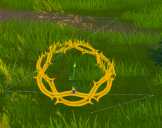
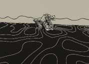
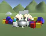
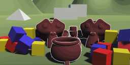
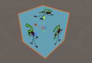
2D SDF Shadows Now that we know the basics on how to combine signed distance functions, we can use them to do cool stuff with them. In this tutorial we’ll use them to render 2d soft shadows. If you haven’t read my previous tutorials about signed distance fields yet, I highly recommend you do that first, starting at the tutorial about how to create simple shapes.
Base Setup I did a simple room setup here, it uses the techniques described in earlier tutorials.
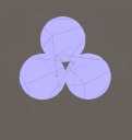
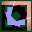
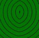
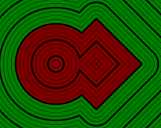
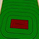
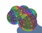
2D SDF Space Manipulation When using polygon assets we can only draw one object at a time (ignoring stuff like batching and instancing), but when working with signed distance fields we aren’t bound by the same limitations, if two positions have the same coordinate, the signed distance functions will return the same value and you can get multiple shapes with one calculation. To learn how to transform the space we use to generate signed distance fields I recommend you understand how to create shapes with signed distance functions and combine sdf shapes.
2D SDF Combination In the last tutorial we learned how to create and move simple shapes with signed distance functions. In this one we will learn how to combine several shapes to make more complex distance fields. I learned most of the techniques described here from a glsl signed distance function library you can find here (http://mercury.sexy/hg_sdf) and there are a few ways of combining shapes I don’t go into here.
Setup To visualise the signed distance fields, we’re going to make one basic setup and then use the operators with it.
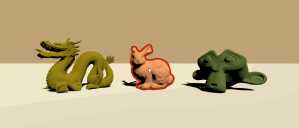
2D Signed Distance Field Basics So far we mostly used polygonal meshes to represent shapes. While meshes are the easiest to render and the most versatile, there are other ways to represent shapes in 2d and 3d. One way which is used frequently is signed distance fields(or SDF). Signed distance fields allow for cheaper raytracing, smoothly letting different shapes flow into each other and saving lower resolution textures for higher quality images.
We’re going to start by generating signed distance fields with functions in 2 dimensions, but later continue by generating and using them in 3d.
Flowing River This tutorial is a case study on how to make a river via a shader. My inspiration for the look was this post by Eris https://twitter.com/Erisdraw3D/status/1056931358185086976.
The Tutorial is done via a surface shader, so if you don’t know how they work it’s best to read the tutorial on surface shaders first.
Transparent Surface Shader We’ll start with a transparent surface shader, for that we’ll have to add the alpha attribute to our surface shader declaration.
Improved Toon Light Last weeks tutorial was about making a simple toon shader, but I felt like there’s still a lot to improve about it so this weeks tutorial is too. We’ll fix a thing, and add multiple steps to the lighting as well as a specular highlight. I recommend you to read the previous tutorial if you haven’t because this one is heavily based on it and expands its code.
Improved shadows for multiple lights.
Single Step Toon Light I thought about how to make a toon shader and this is the result. There are obviously many different toon styles, so this is just one possiblity of many, but even if it’s not the result you want in your game this tutorial can give you some insight in how I work and how to do stuff with shaders. The main advantage for me to use this toon shader in opposition to one that reads from ramp texures is that I can dynamically change the parameters without editing a texture first.
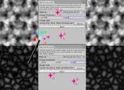
Baking Shaders into Textures Calculating everything ony the fly in the shader gives us the most flexibility and is even needed for many effects, but if we don’t need the noise to be dynamic we can save it to a texture to save a lot of performance in the shader. You can bake all shader output into textures as long as it doesn’t depend on external parameters like object position or lighting.
We’re going to make a little editor tool in this tutorial that can be used to bake any shader output into a texture, but I’ll work with noise functions for now, because they can be kinda expensive and are easily repeatable which allows us to use smaller textures.
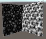
Tiling Noise So far we generated noise that goes on forever. But in some cases we want noise that repeats itself after a certain distance though, mainly when we’re baking noise into a texture. In this tutorial I’ll show you how to make noise repeat and how to use uv coordinates instead of worldspace positions for noise generation.
I use the layered perlin noise and voronoi noise to show the theory behind tiling noise, but it’s possible to use those patterns with many different types of noise and other shaders as well.
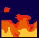
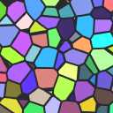
Voronoi Noise Summary Another form of noise is voronoi noise. For voronoi noise we need a bunch of points, then we generate a pattern based on which point is the closest. This specific implementation of voronoi noise will work based on cells just like most of the previous noise types we explored, this makes it relatively cheap and easy to repeat. To understand this tutorial I recommend you to have at least understood the basics of shaders in unity and how to generate random values in shaders.
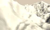
Layered Noise Layered Noise So far the noise we generated always looked either very soft, or very noisy. We can improve that by layering multiple layers of noise on top of each other. That way we get the structure of the soft noise as well as the interresting details of the more high frequency noise. Layering noise works well for value noise as well as perlin noise. While layering noise might give you patterns that are closer to what you intend to see, you also have to be careful if you worry about performance because each layer of noise you add costs you about as much performance as the first.
Perlin Noise Perlin Noise One of other common form of noise is perlin noise. Perlin noise is one implementation of so called “gradient noise” similarly to value noise it’s based on cells so it can be easily repeated and looks smooth. What differentiates it from value noise is that instead of interpolating the values, the values are based on inclinations. Because noise in general is a pretty complex topic I recommend you to read the tutorials on white noise and value noise first.
Value Noise Summary In the last tutorial we learned how to generate random numbers in a shader. In this one we’ll go into interpolating between random numbers to generate noise that’s smoother and gradually changes. Because we need random values to interpolate between for value noise, you should know how to generate random values in shaders before doing this tutorial. Value noise is similar to perlin noise, but different because we always interpolate between the center of the cells, perlin noise will be explained in a later tutorial.
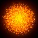
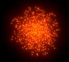
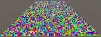
White Noise Summary For many effects we want random numbers to generate patterns or other things in our shaders. Directly using those random values generates a pattern we call “white noise”. There are other patterns which have more structure we can generate based on that which we will explore in other tutorials, for example perlin and voronoi noise. For this tutorial we will implement the noise in a surface shader so you should know how to write a basic surface shader).
Blur Postprocessing Effect (Box and Gauss) Summary A effect that’s useful for example to show exhaustion or to make transitions is a blur. To blur the screen we take the average of the surrounding pixels. You can use the effect in many places, but the easiest and most straightforward is probably as a postprocessing effect, so it’s best for you to know how to write postprocessing effects before doing this tutorial.
Boxblur The easiest form of a blur is a box blur, it just takes the average of a square area and displays it.
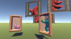
Stencil Buffers Summary The depth buffer helps us compare depths of objects to ensure they occlude each other properly. But theres also a part of the stencil buffer reserved for “stencil operations”. This part of the depth buffer is commonly referred to as stencil buffer. Stencil buffers are mostly used to only render parts of objects while discarding others.
The stencil buffer is also used by unity internally for the deferred graphics pipeline, so if you do deferred rendering, some limitations apply.
Clipping a Model with a Plane Summary Another cool effect is to make the surface disappear when it’s beyond a certain plane.
To follow this tutorial, it’s best to know how surface shaders work - you can find a tutorial how they work here.
Define Plane We start by creating a new C# script which will define the plane we use later and pass it to the shader. It has a material as a public variable which we will pass the plane to.
Hull Outlines Summary So far we only ever wrote a color to the screen once per shader (or let unity generate multiple passes for us via surface shaders). But we have the possibility to draw our mesh multiple times in a single shader. A great way to use this is to draw outlines. First we draw our object as usual and then we draw it again, but we change the vertices a bit so it’s only visible around the original object, drawing a outline.
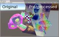
Outlines via Postprocessing Summary One of my favourite postprocessing effects are outlines. Doing outlines via postprocessing has many advantages. It’s better at detecting edges than the alternative (inverted hull outlines) and you don’t have to change all of your materials to give them the outline effect.
To understand how to create outlines via postprocessing it’s best to have understood how to get access to the depth and normals of the scene first.
Depth Outlines We start with the shader and C# script from the postprocessing with normals tutorial.
Postprocessing with Normal Texture Summary Another piece of information we can easily get our hands on thats very useful for postprocessing is the normals of the scene. They show in which direction the surface at any given pixel is pointing.
To understand how to get and use the normals of the scene it’s best to know how to access the scene depth first, I made a tutorial on how to do that here.
Read Depth and Normals We start this tutorials with the files from the depth postprocessing tutorial and expand them as we need.
Postprocessing with the Depth Texture Summary In the last tutorial I explained how to do very simple postprocessing effects. One important tool to do more advanced effects is access to the depth buffer. It’s a texture in which the distance of pixels from the camera is saved in.
To understand how postprocessing effects with access to the depth buffer work it’s best to understand how postprocessing works in general in unity. I have a tutorial on that here.
Postprocessing Basics Summary We used all shaders we wrote in this tutorial until now to render models to the screen. Another way shaders are commonly used is to manipulate images with them. That includes the image we’re drawing to the screen as we render our game. When manipulating the render output after we rendered our objects to the screen it’s called postprocessing.
Postprocessing still uses the same shader language and structure as shaders that render surfaces, so I’d recommend you to know how to render surfaces first.
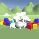
Vertex Displacement Summary So far we only used the vertex shader to move vertices from their object coordinates to their clip space coordinates (or to the world space coordinates which we then used for other things). But there are more things we can do with vertex shaders. As a introduction I’m going to show you how to apply a simple sine wave to a model, making it wobble.
I will make the shader with a surface shader so you should know the basics of surface shaders, but it works the same with any other type of shader.
Polygon Clipping Summary Of course everything we render so far is made of polygons, but someone asked me how to clip a polygon shape based on a list of points in a shader so I’ll explain how to do that now. I will explain how to do that with a single shader pass in a fragment shader, a different way would be to actually generate triangles based on your polygon and use stencil buffers to clip, but I won’t explain that in this tutorial.
Custom Lighting Summary Surface shaders are wonderful and being able to use the Standard PBR model is very powerful. But we don’t always want the PBR light. Sometimes we want to change the way we treat lighting to get a different, often more cartoonish, look. Custom lighting functions allow us to do exactly that.
This tutorial is about a surface shader specific feature, while the basics of lighting are the same in all shaders, you need a lot more code to archieve the same result from a non-surface shader and I won’t explain it in this tutorial.
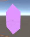
Fresnel Summary A common effect people use in shaders in a fresnel effect. With a fresnel you can darken, lighten or color the outline of your objects, increasing the sense of depth.
For this tutorial we will make a surface shader, so if you follow it directly you should know the basics of surface shaders. You can find a explanation of them here. But you can also use a fresnel effect for unlit shaders, giving your objects some smoothness and tangibility without having to implement expensive lighting.
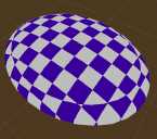
Checkerboard Pattern Summary For me, one of the most interresting things to do with shaders is procedural images. To get started with that, we’re going to create a simple Checkerboard pattern.
This tutorial will build on the simple shader with only properties, but as always, you can also use the technique to generate colors in more complex shaders.
Stripes I will take the world position of the surface to generate the chessboard texture, that way we can later move and rotate the model around and the generated patterns will fit together.
Triplanar Mapping Summary I made a tutorial about planar mapping previously. The biggest disadvantage of the technique is that it only works from one direction and breaks when the surface we’re drawing isn’t oriented towards the direction we’re mapping from (up in the previous example). A way to improve automatic uv generation is that we do the mapping three times from different directions and blend between those three colors.
This tutorial will build upon the planar mapping shader which is a unlit shader, but you can use the technique with many shaders, including surface shaders.
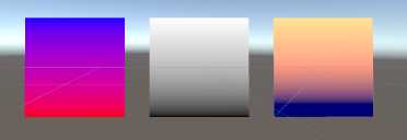
Color Interpolation Summary Often you have more than one color going into the output you want to draw to the screen. A simple way of combining two colors is to interpolate between them based on other parameters.
This tutorial will build on the simple textured shader, but you can use this technique with any shader including surface shaders. Interpolate Colors The first version of this shader we’re exploring will just interpolate between two plain colors based on a value.
Planar Mapping Summary Sometimes you don’t have texture coordinates on your object, you want to make the Textures of multiple Objects align or you have a different reason to generate your own UV coordinates… In this tutorial we’ll start with the simplest way to generate your own coordinates, planar mapping.
This tutorial will build on the simple textured shader, but you can use the technique with any shader including surface shaders.
Basics We start by removing the uv coordinates from the input struct as we’ll generate our own texture coordinates.
Sprite Shaders Summary In unity the way sprites are rendered is very similar to the way 3d objects are rendered. Most of the work is done by the sprite renderer component. I’ll go a bit over what the component is doing and how we can change our shader to do some of the stuff the default sprite renderer is doing.
This tutorial will build on the transparent shader we made previously so it’s best that you understand that one first.
Basic Transparency Summary In addition to just painting color onto the screen, we can also preserve some of the color that was on the screen previously, making the object seem see-through. I’ll explain how we can archieve this effect in a basic shader without lighting.
To understand how to implement transparency, I recommend you know the basics of writing shaders, in this tutorial I’ll start with the result of the tutorial for implementing textures.
Surface Shader Basics Summary In addition to writing shaders almost from the ground up, unity also allows us to define some parameters and let unity generate the code which does the complex light calculations. Those shaders are called “surface shaders”.
To understand surface shaders, it’s good to get to know basic unlit shaders first, I have a tutorial on them here.
Conversion to simple Surface Shader When using surface shaders we don’t have to do a few things we have to do otherwise, because unity will generate them for us.
Basic Shader Summary In the last three tutorials I explained some of the cornerstones of how shaders work. In this one I show you how to fill in the rest.
The main thing I didn’t show was actual executed code. Thats because you don’t need much code to get a shader running at first and all of the fancy code is in specialized tutorials.
What we have so far Everything here should be explained in one of the previous three tutorials.
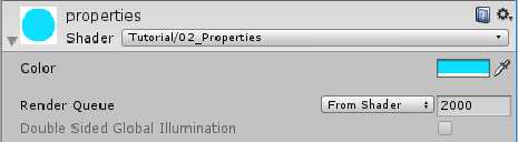
Variables Summary After making clear how the shader stages are put together and the rough outline of shaderlab outside of the actual shader code, lets talk about what variables our shader needs to function and how we add them to our code. This includes the variables that we set per material, the variables that are part of the mesh data and the data thats passed from the vertex to the fragment.
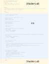
HLSL HLSL? Hlsl is the language the “juicy” parts of unity shaders are written in. The parts that contain custom logic and eventually decide what is drawn where on screen. It’s the language Microsoft designed to work with their Direct3D API to write gpu programs. Strictly speaking most Unity shaders are tagged as being written in CG which is short for C for Graphics, but CG shares most of it’s syntax and features with hlsl and was deprecated in 2012, so wrongly referring to it as hlsl leads to you being able to find better results in search engines and not much else.
Structure Shader Structure When talking about shaders I want to start at explaining the rough outline of how shaders are set up so we can understand how to customize them.
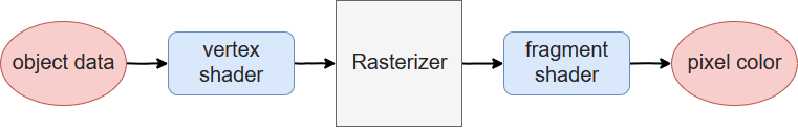
Most modern shaders have a variable pipeline that consists out of at least a vertex shader and a fragment shader. It’s also possible to add a geometry and tesselation stage to this, but you only rarely need those. The vertex shader (sometimes also called vertex stage or function) takes the data that defines the model and transforms it into screenspace so it can be rendered (using matrix multiplication, but we can just accept that it works for now).